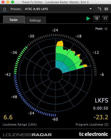
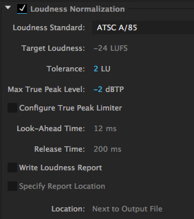
The second ring indicates the Target Loudness setting (based on the settings in the Loudness Radar). The other rings help you measure the on-going loudness of your project. The lower right corner indicates the average level of your entire project, measured in LKFS or LUFS (based on the settings in the Loudness Radar). Custom Auto-Match Loudness settings in Adobe Premiere Pro CC The Essential Sound panel makes editing audio easy but it's missing the ability to customize the.
- Adobe Premiere Loudness Radar Software
- Loudness Radar In Adobe Premiere
- Adobe Premiere Loudness Radar Loop
The attached image displays a processing workflow designed to optimize Spoken Word intelligibility. The workflow also demonstrates a realtime example of Integrated Loudness/Maximum True Peak compliance targeting.
There are 7 reference point Sections worth noting:
Section A includes the Adobe Audition Effects Rack Signal Level Meters indicating the source (Input) level and the (Output) level. The Output level reflects the results of the workflow’s inserted plugins. The chain includes a Compressor, a Limiter, and a Loudness Meter. Note the level meters indicate signal level. They do not indicate or represent perceptual Loudness.


Section B displays the gain reduction applied by the Compressor at the current position of the playhead. For the test/source audio I determined an average of 6dB of gain reduction would yield acceptable results. The purpose of this stage is to reduce the dynamic range and/or dynamic structure of the Spoken Word resulting in optimized intelligibility AND to prevent excessive down stream limiting. This is an important workflow element when preparing Spoken Word audio for Internet/Mobile, and Podcast distribution.

Section C includes my subjective limiting parameters. The Limiter will add the required amount of gain to achieve a -16.0 LUFS deliverable while adhering to a -1.5 dBTP (True Peak Max). If the client, platform, or workflow requires an alternative Loudness target and/or Maximum True Peak ceiling – the parameters and their mathematical relationship may be altered for customized targeting. Please note the Maximum True Peak referenced in any spec. is more of a ceiling as opposed to a target. In essence the measured signal level may be lower than the specified maximum.
Section D indicates the amount of limiting that is occurring at the current position of the playhead.
Section E displays the user defined Integrated Loudness target located above the circular Momentary Loudness LED (12 o’clock position). The defined Integrated Loudness target is also visually represented by the Radar’s second concentric circle. The Radar display indicates the Short Term Loudness measured over time within a 3 sec. window. The consistency of the Short Term Loudness is evident indicating optimized intelligibility.
Adobe Premiere Loudness Radar Software
Section F displays the unprocessed source audio that lacks optimization for Internet/Mobile, and Podcast distribution. Any attempt to consume the audio in it’s current state in a less than ideal listening environment will result in compromised intelligibility. Mobile device consumption in like environments will exacerbate compromised intelligibility.
Loudness Radar In Adobe Premiere

Section G displays the processed/optimized audio suitable for the noted distribution platform. The Integrated Loudness, True Peak, and LRA descriptors now satisfy compliance targets. Notice there is no indication of excessive limiting.
Adobe Premiere Loudness Radar Loop
-paul.
